Wood Cutting Mode
Wood Cutting mode is a specialized version of 1D linear cutting designed specifically for timber, structural lumber, and dressed wood. It adds cross-section type matching and dimension-aware grouping that makes it the right tool for carpentry, timber framing, joinery, and furniture making.
What Makes Wood Mode Different
Timber cutting has a few constraints that generic 1D cutting does not handle:
- Cross-section matching — A 90×45 mm stud and a 190×45 mm joist are both linear pieces, but they cannot come from the same stock. Wood mode lets you define cross-sections and ensures pieces only come from matching stock.
- Grain direction — For structural and appearance-grade timber, pieces must be cut with the grain running along the length. In Wood mode this is inherent: parts are cut to length along the bar and never rotated.
- Timber profile visualisation — The canvas shows each timber with its cross-section shape, making it easy to verify that the right profile is being used.
For non-timber linear materials (steel, aluminium, plastic, cable), use 1D Linear Cutting mode. Wood mode adds timber-specific fields that are unnecessary and may create confusion for non-timber materials.
Cross-Section Types
Wood mode organises timber by cross-section type. This affects how pieces are grouped in the cut list and how they appear in the canvas.
| Cross-section type | Typical dimensions | Examples |
|---|---|---|
| Column | Width ≈ Depth (square or near-square) | 90×90, 140×140, 150×150 posts |
| Board | Width > 2× Depth | 190×35, 240×45, 290×45 framing boards |
| Batten | Width > Depth, but < 2× | 70×45, 90×45, 90×35 studs and plates |
| Lath | Width > 3× Depth | 75×19, 100×25, 50×12 lath and cover strip |
When you add a stock length or demand piece, you select its cross-section type from a dropdown. CutOptim automatically groups pieces into categories and only assigns demand pieces to stock of the matching cross-section and dimensions.
Adding Timber Stock
| Feature | Type | Description |
|---|---|---|
| Length | number | Full length of the timber piece in mm or cm. |
| Width | number | Cross-section width (larger of the two cross-section dimensions for boards and battens). |
| Depth (Thickness) | number | Cross-section depth (smaller dimension). For a 90×45 stud, depth is 45 mm. |
| Cross-section type | select | Column, Board, Batten, or Lath. Controls grouping and visual representation. |
| Quantity | integer | Number of pieces of this stock available. |
| Price | number | Cost per piece for quotation export. |
| Label | text | Optional label, e.g. 'MGP10 90×45 3.6m'. |
Example timber stock for a deck frame:
| Label | Length | Width | Depth | Type | Qty |
|---|---|---|---|---|---|
| MGP10 90×45 4.8m | 4800 | 90 | 45 | Batten | 20 |
| MGP10 140×45 4.8m | 4800 | 140 | 45 | Board | 10 |
| H3 90×90 3.6m | 3600 | 90 | 90 | Column | 6 |
Adding Parts to Cut
| Feature | Type | Description |
|---|---|---|
| Length | number | Required cut length. |
| Width | number | Required cross-section width. Must match an available stock cross-section. |
| Depth | number | Required cross-section depth. Must match an available stock cross-section. |
| Cross-section type | select | Must match the cross-section type of the intended stock. |
| Quantity | integer | Number of pieces required. |
| Label | text | Piece name, e.g. 'Joist J1', 'Bearer B3'. |
| Cross-section | number | Width × height of the part. It must match a stock cross-section exactly — parts with no matching stock are reported after the run rather than cut from a different profile. |
If a part’s cross-section (width × depth) matches no stock cross-section, the optimization still runs — the unmatched parts are reported afterwards in the results, and in the PDF, as cross-sections with no matching timber. Check that your part cross-sections exactly match your stock cross-sections.
Running a Wood Mode Optimization
- 1
Switch to Wood mode
Click the **Wood** tab in the mode selector at the top of the toolbar.
- 2
Add stock timber
In the Stock table, add your available timber lengths with cross-section dimensions and quantities. Use the cross-section type dropdown to classify each entry.
- 3
Add demand pieces
In the Parts to cut section, click + Part and add each required piece. Ensure the cross-section dimensions exactly match the stock — a part whose cross-section matches no stock entry is reported after the run instead of being cut.
- 4
Configure kerf
In Settings, set the kerf width for your saw. A standard handsaw or circular saw produces 2.5–3.5 mm kerf. A precision cabinet saw may be 2 mm.
- 5
Run the optimization
Click Run optimizer at the bottom of the left sidebar. CutOptim groups demand pieces by cross-section and optimizes each group independently against matching stock.
- 6
Review results by cross-section
The canvas shows results grouped by cross-section type. Use the group tabs to navigate between Columns, Boards, Battens, and Laths. Each group shows bar diagrams for the matching stock.
Reading Wood Mode Results
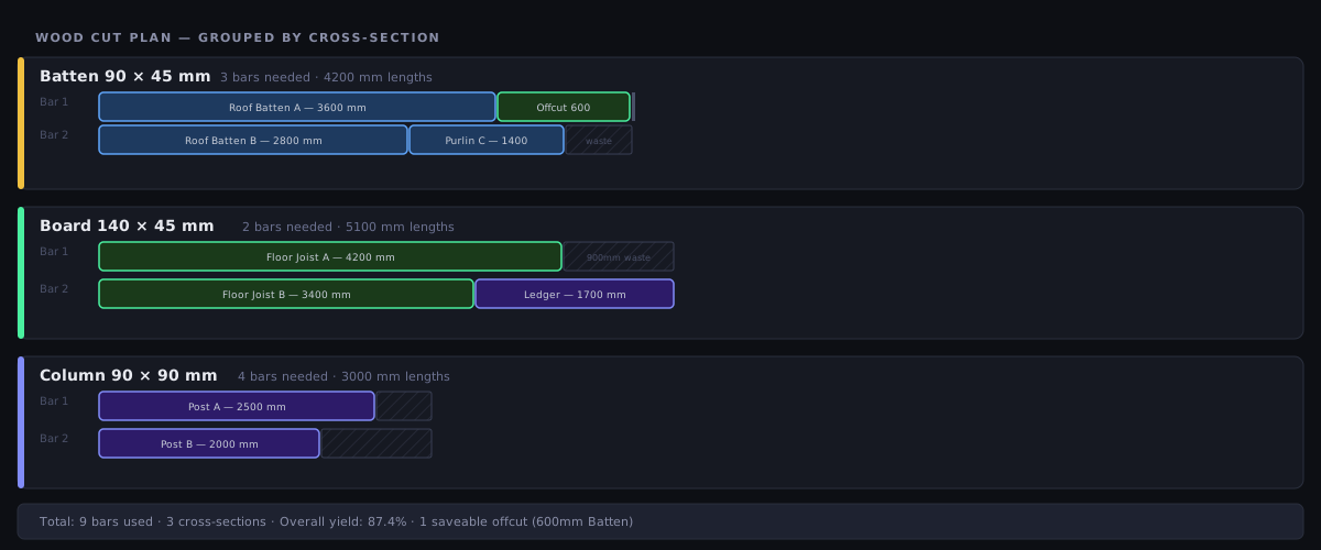
Results are organised into cross-section groups. For each group, you see:
- Bars used from that stock section
- Pieces placed from the demand list
- Offcuts per bar, including their length and cross-section
- Yield % for that section
The overall summary at the bottom aggregates across all groups and shows total timber used, total waste, and total material cost.
Offcuts in Wood Mode
Offcuts in Wood mode include their full cross-section dimensions, so when you save them to the Offcut Inventory, they are searchable by cross-section in future jobs. A saved offcut of 90×45 mm will only appear as available stock for future 90×45 demand pieces.
The Sawing Plan Pro
The bar diagrams show what comes off each length of timber. The sawing plan tells you where to stop the blade, in order — which is the arithmetic nobody wants to repeat twenty times down a 4.8 m stick.
A piece of timber has no cut tree: it is cross-cut end to end from the head. So the plan is simply the running offset — after each part the blade drops at that mark, then advances by the kerf.
The steps on each length, in the order you make them
- The calibration skim, if it is switched on. It always comes off the head — the start of the length.
- The start-trim head cut, if a start trim is set.
- One step after each part — except a last part that finishes flush with the usable end when there is no end trim, because there the timber simply stops and no pass is needed.
Every step gives a stop position measured from the head: a number you can set on a stop, not a part length to add up. Head passes are named as such (Calibration, Start trim) and leave the order column blank, because they free no part. There is no stage number and no cut direction — timber is crossed the same way every time, and it is never turned.
Wood reports a cut length without being asked. Because the cross-section is known per material, the distance the blade travels across the piece can be measured, so the sawing plan reports a sawn length in the PDF key figures and in the Excel tab — whatever mix of sections the job holds. 1D Linear carries no section of its own; it reports stop positions only, unless you set its optional Profile width, which is a single width applied to the whole job. That is the reason to reach for Wood mode on a job with several sections: one number cannot describe five profiles.
On screen
- The Cutting Sequence bar sits directly above the bar strips it steps through, ahead of the first cross-section box. Its controls are ◀ Previous, the step readout, ▶ Next, ⏮ Restart and ▶ Play (0.8 s per step, stopping at the last one).
- Below the cut list, the whole plan is listed as a Cutting Sequence table with the columns Order, Bar, Name and Position. Clicking a row jumps the player to that step, and the active row is highlighted, so the table and the player stay one thing.
- On each strip the cut marks light up as you step: the current one solid, completed ones faded, upcoming ones hidden.
Because every step on a length is a single pass of the blade, the number of steps equals the Cuts figure in the results header, whatever your trim and calibration settings.
In the exports
- PDF — a Sawing plan page of its own, with the columns
#, Bar, Order, Name and Position, plus a framed strip of key figures (cuts and the sawn length) under the table. - Excel (.xlsx) — a Cutting Sequence tab straight after the Cut list tab, with a Cut length column and the totals repeated at the bottom, so the tab stands alone at the saw.
Both need Pro, like the on-screen player. See Cutting Sequence and Exports & Downloads.
Calibration Cut Pro
A calibration cut skims a thin strip off the head of every length before any part is cut. You measure the strip, compare it with the number you asked for, and correct the stop by the difference — so the first real part is already accurate instead of being the one you sacrifice to find out the setup was off. On rough-sawn or site-stored timber, where the end is as likely to be out of square as it is to be split, that first strip is worth the material.
- The four-edge side picker you may have seen in 2D is hidden here. Timber has one head, so a choice of four edges would be a control the plan could not honour.
- It rides on the start trim: the material reserved is start trim + calibration, which is what makes step 0 of the sawing plan a real stop position.
- With both a start trim and a calibration cut set, the head is crossed twice — once for the strip you measure, once to take the rest of the trim off — and the sawing plan lists both passes.
See Settings for the control itself.
Grain Matching Workshop
Grain matching works in 2D Panel mode only — it has no effect in Wood mode. The groups are built from the 2D parts list and only the panel optimizer reads them, so a group you create will not influence a wood cutting plan. This section is here because grain matters most in timber; if you need it today, lay the parts out in 2D Panel mode. See Grain Matching for how it behaves there.
Grain matching keeps pieces that must share the same grain character — knot pattern, colour, ring structure — on the same board. It is what you want for a wardrobe with two adjacent doors that should read as one piece of timber, a table top made from several matched planks, or a stile-and-rail set for cabinet doors.
What Wood mode does offer today
Wood mode’s own grain-relevant behaviour is the cross-section match: a part is only ever cut from stock of the same cross-section, so a 50×100 rafter never comes out of a 50×150 board. Length pieces are not rotated in this mode — a part is cut to length along the bar — so grain direction along the length is preserved by the nature of the cut, with no setting to configure.
Name your groups descriptively. Matched pair 1 and Matched pair 2 are hard to track on a complex job. Living room cabinet doors or Island bench ends are immediately clear when you return to the project.
Practical Example: Pergola Frame
Job: Freestanding backyard pergola, 4×4 m.
Parts:
- 4× 90×90 posts at 2700 mm (Column)
- 2× 140×45 bearers at 4200 mm (Board)
- 5× 90×45 rafters at 4200 mm (Batten)
- 4× 90×45 noggings at 600 mm (Batten)
Stock available:
- 6× 90×90 H3 treated pine, 4800 mm
- 4× 140×45 MGP10, 4800 mm
- 8× 90×45 MGP10, 4800 mm
Result — with a 3 mm kerf and no kerf tolerance:
- Posts: 4 bars used (of 6 available), each leaving a 2100 mm offcut
- Bearers: 2 bars used, 600 mm left over per bar
- Rafters + noggings: 6 bars used — five bars each take one 4200 mm rafter and leave exactly 600 mm, but a 600 mm nogging needs 600 mm plus the 3 mm kerf, so all four noggings are pushed onto a sixth bar
- 12 bars in total, 74.0% yield
This is the classic near-miss, and it is worth understanding before you buy timber. Turn on a 3 mm kerf tolerance (Kerf & Tolerance) and CutOptim is allowed to treat that 3 mm shortfall as acceptable: the noggings drop onto the rafter bars, those five bars come out at 0 mm remainder, and the job finishes in 11 bars at 80.7% yield — one whole bar saved by a single setting.
Even 80.7% understates what you keep: 8400 mm of the leftover is the four 2100 mm post offcuts, which are long enough to be worth saving to the offcut inventory and cutting from on the next job.